The structure and cross-linking method of cross-linked power cable
Cross-linked power cable of structure and cross-linking method
One. basic structure
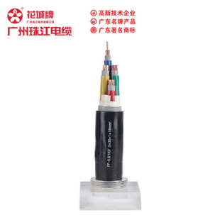
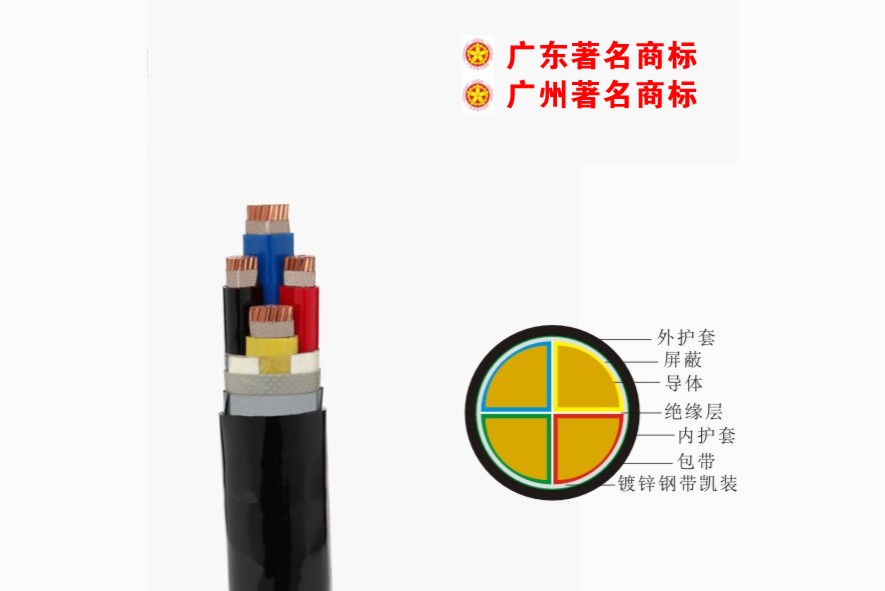
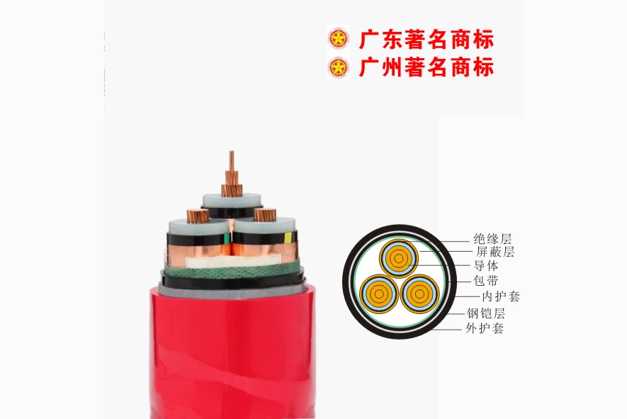
Cross-linked cables are generally composed of three parts: conductor, insulation and sheath.
1. Conductor
A conductor refers to an object that can conduct current, and is also called a conductive core. The material used as wire and cable conductor must first have good electrical conductivity, that is, the resistance must be small to reduce the loss of current on the line. Loss is directly related to the size of the current and the size of the resistance, and is manifested in the heating of the conductor.
Cables use conductors to conduct current, so the specifications of wires and cables are expressed by the cross-section of the conductor.
The conductor of the power cable can be made as a whole solid, or formed by twisting a plurality of single wires, and the shape can be round or fan-shaped. The twisted cores can be used in two types: non-compacted and compressed cores. The conductive core of the cross-linked cable usually adopts a twisted structure, and the 1kV cross-linked cable usually adopts a sector shape, a semicircular shape and a circular shape. Cross-linked cables above 6kV use round compact cores.
(1) Round conductive core
For round conductive cores, the twisting arrangement generally adopts the form of "regular twisting", and the twisting principle is:
1) The center is generally a single wire, the second layer is six single wires, and each layer has six more than the inner layer, and the single wires use the same wire diameter.
2) The stranding direction of each layer of single wires should be opposite to the direction of the previous layer, and the outermost layer should be twisted to the left. This structure can ensure the stability and certain flexibility of the conductive core of the cable.
(2) Sector-shaped and semi-circular conductive cores
Fan-shaped and semi-circular conductive cores are not ideally symmetrical. Therefore, it is extremely important to consider the stability under bending when designing the arrangement of multiple cores. In order to make the non-compressed sector core have sufficient flexibility and stability, the following rules must be observed when designing the non-compressed sector core:
1) The central conductor of the regular fan-shaped core must be located on the center line of the fan-shaped core. Otherwise, when the core is bent, the upper conductor on the center line will be stretched, and the lower part will be compressed and may be extruded. Cause sector damage and damage the insulation.
2) Slippage rule The diameter of the wire on the centerline of the sector core is generally larger, and the wires on both sides of it should be able to slide along the centerline without changing the shape of the sector core. This rule is called the slippage rule, otherwise, When the sector core is twisted into a cable, the sector may be destroyed and damage the insulation
2. Insulation
Insulation is made by wrapping the insulating material on the outside of the conductor with different thicknesses according to the requirements of its withstand voltage level, which plays a role in isolating the charged body from other parts. The material of the insulating layer must have good electrical insulation performance, which is mainly manifested in the magnitude of the withstand voltage. Generally speaking, the thicker the insulating layer of the same quality, the higher the withstand voltage.
Insulation must also have certain mechanical and physical properties and processing and manufacturing process properties. For example, in the manufacture of low-voltage cables, although a very thin insulation can be used in terms of electrical performance, a slightly thicker one is better in terms of mechanical properties and processing technology. The reason is that the insulation is too thin, processing is difficult, and easy to damage. After the cable is energized, the conductor will heat up. Therefore, an ideal insulating material should have good insulating properties and good thermal conductivity.
Insulation will change internally under the action of electricity and heat, and the insulation performance will decrease over time. Cross-linked polyethylene has excellent electrical insulation properties. After cross-linking, its heat resistance and mechanical properties are greatly improved, making it an ideal insulation material at present.
After the conductor is covered with an insulating layer, it is called an insulated core. The insulation layer on each conductor is called core insulation or core insulation for short.
According to national standards GB12706 and GB11017, the insulation thickness of cross-linked cables of different voltage levels is shown in Table 1-1.
Table 1-1 Insulation thickness of cross-linked cable
Nominal Conductor | Cable insulation thickness under different working voltages(mm)kV | |||||||
Section (mm2) | 0.6/1 | 3.6/6 | 6/10 | 8.7/10 | 12/20 | 21/35 | 26/35 | 64/110 |
25 | 0.9 | 2.5 | 3.4 | 4.5 | 5.5 | 9.3 | 10.5 | |
35 | 0.9 | 2.5 | 3.4 | 4.5 | 5.5 | 9.3 | 10.5 | |
50 | 1.0 | 2.5 | 3.4 | 4.5 | 5.5 | 9.3 | 10.5 | |
70 | 1.1 | 2.5 | 3.4 | 4.5 | 5.5 | 9.3 | 10.5 | |
95 | 1.1 | 2.5 | 3.4 | 4.5 | 5.5 | 9,3 | 10.5 | |
120 | 1.2 | 2.5 | 3.4 | 4.5 | 5.5 | 9.3 | 10.5 | |
150 | 1.4 | 2.5 | 3.4 | 4.5 | 5.5 | 9.3 | 10.5 | |
185 | 1.6 | 2.5 | 3.4 | 4.5 | 5.5 | 9,3 | 10.5 | |
240 | 1.7 | 2.6 | 3.4 | 4.5 | S.5 | 9.3 | 10.5 | 19.0 |
300 | 1.8 | 2.8 | 3.4 | 4.5 | 5.5 | 9.3 | 10.5 | 18.5 |
400 | 2.0 | 3.0 | 3.4 | 4.5 | 5.5 | 9.3 | 10.5 | 17.5 |
500 | 2.2 | 3.2 | 3.4 | 4.5 | 5.5 | 9.3 | 10.5 | 17.0 |
630 | 2.4 | 3.2 | 3.4 | 4,5 | 5.5 | 9.3 | 10.5 | 16.5 |
800 | 2.6 | 3.2 | 3.4 | 4.5 | 5.5 | 9.3 | 10.5 | 16.0 |
1000 | 2.8 | 3.2 | 3.4 | 4.5 | 5.5 | 9.3 | 10.5 | 16.0 |
1200 | 3.0 | 3.2 | 3.4 | 4.5 | 5.5 | 9.3 | 10.5 | 16.0 |
3. Protective layer
The sheath is the protective part of the outer layer of the cable. According to the purpose of the cable, the use environment and the insulation, there are many different types and structures of the sheath, and they play different roles. There are two main types of XLPE cable sheath: bare sheath and armored type. Under the condition of not being subjected to mechanical external force, the bare sheath is selected, that is, a layer of plastic is extruded directly outside the insulated core. If it is used for direct burying or To withstand certain mechanical external forces, it needs to be covered with metal tape armor; when 110kV high voltage cross-linked cables or other cables are buried underwater, they need a waterproof sheath, covered with a lead sheath, aluminum sheath or aluminum-plastic composite waterproof layer.
Because it cannot withstand mechanical damage, it needs to be covered with steel wire and steel belt. Steel wires and steel belts are easily corroded, and lead sleeves and aluminum sleeves are also prone to corrosion in harsh environments. Therefore, various anti-corrosion materials, such as asphalt, jute, plastic, etc., must be covered. These are collectively referred to as the outer sheath. Among them, steel wires and steel belts are called armor layers, and asphalt, jute, and plastics are called protective layers. In addition, on the conductor, the insulation layer, the cable core or the outer layer of the wire and cable, in order to prevent external electromagnetic wave interference or function as a uniform electric field, it is also covered with metal tape, wire or semi-conductive plastic and other materials. These are called shielding layers.
4. Waterproof layer of high voltage cable
Oil-paper cables use lead presses and aluminum presses to extrude metal sleeves. For medium and low-voltage cross-linked cables, they are generally used in chemically corrosive environments or when they are laid under water. However, metal sheaths are generally required for high-voltage cables. The use of extruded corrugated aluminum sheath is ideal, but a continuous aluminum press is expensive. With the development of welding technology, the reliability of the use of corrugated welded aluminum sheath cables has become more and more recognized by people. The cable enterprise adopts advanced argon arc welding technology, and is equipped with on-line inspection devices such as ultrasonic to ensure the sealing of welding. In order to check whether the welding is missing, the manufacturer has added an intermediate inspection device to remove the entire welded cable. Carry out immersion air tightness test, and carry out 100% inspection.
2). Cross-linking method
Although there are many varieties of cross-linked insulation, they are mainly divided into two categories: physical cross-linking and chemical cross-linking. Physical cross-linking is also called radiation cross-linking, and is generally suitable for low-voltage cables with thinner insulation. Medium and high voltage cables generally use peroxide cross-linking, that is, linear molecules are chemically cross-linked to react to convert them into a three-dimensional network structure. Chemical crosslinking can generally be divided into peroxide crosslinking and silane grafting crosslinking. The chemical cross-linking method is simpler than the high-energy radiation cross-linking process, and the operation is safer. The cross-linking degree of radiation cross-linked polyethylene is about 70%, and the chemical cross-linking can reach 70-90%.
1). Irradiation cross-linking
In 1960, Rachem developed the radiation cross-linked cable. This method does not require the addition of a crosslinking agent. In the early 1950s, the United States had discovered the use of radioactive isotopes, reactor waste, reactor radiation itself, and energy from electron accelerators to crosslink polyethylene. It was later discovered that only the high-energy rays produced by the electron accelerator have sufficient intensive radiation power and efficiency, and can be used for wire and cable manufacturing.
Irradiation is the use of high-energy particle rays (such as beta rays) to irradiate linear molecular polymers to open a number of free radicals on their chains, which are referred to as junctions for short. The contact point is very active and can cross-connect two or several linear molecules. Radiation cross-linking is generally suitable for low-voltage cables with thinner insulation. Its main advantages are:
(1) Fast production speed and small space occupation;
(2) There are many types of processable materials, such as PE, PVC, CPE, PP, almost all polymers, and a wide variety of products;
(3) The product has better heat resistance, wear resistance and higher electrical properties; it is flame retardant;
(4) Low power consumption.
But there are also some problems:
(1) Large one-time investment in equipment;
(2) The irradiation of large cross-section cables is uneven. After repeated irradiation, the cable is bent too many times, which is not suitable for the production of cables of 10kV and above. It is mainly suitable for electrical equipment cables, and it is also possible for cables with smaller cross-sections and lkV~10kV overhead cables.
(3) The equipment operating rate is low.
Two), peroxide cross-linking
The peroxide crosslinking method is a method of initiating crosslinking by adding a crosslinking agent. Its main advantage is that it is suitable for the production of cross-linked polyethylene insulated power cables of various voltage levels and various cross-sections, especially medium and high voltage cables of 35kV and above.
1. Steam crosslinking (SCP)
The steam cross-linking manufacturing technology is one of the most "oldest" cross-linking methods evolved from the background of continuous rubber vulcanization technology. This method uses superheated steam with a pressure of 15-20 kg/cm2 and a temperature of 180-200°C as the heating and pressurizing medium to achieve cross-linking of polyethylene. Steam cross-linking was successfully researched by GE in 1957. Japan's Sumitomo Electric Company introduced this technology in 1959 and put it into production in 1960.
Since the water vapor directly contacts the molten polyethylene in the cross-linked pipe, the water will penetrate and diffuse into the insulation. During the cable cooling process, the water vapor inside the insulation reaches a saturated state to form micropores, which in turn triggers tree discharge. This is the Achilles heel of this method. In addition, the pressure in the cross-linked tube is directly related to the temperature. To increase the temperature, the pressure must be increased at the same time. For every 10°C increase in temperature, the pressure will increase by 5kg, which is practically impossible. Moreover, steam cross-linking requires 200-300 kilograms of steam per hour, which is equivalent to 200-300 kW of electrical energy. As a result, some new dry cross-linking processes have appeared since the 1960s.
2. Infrared crosslinking method (RCP) and dry crosslinking
Infrared cross-linking method is also called thermal radiation cross-linking method (RCP), which is a dry cross-linking process invented by Sumitomo Electric Corporation of Japan in 1967.
The method of using infrared rays to crosslink polymers was patented by General Electric (GE) in France as early as 1937 for the vulcanization of rubber products. In 1961, American Gray (w.R. Grace) obtained a patent for manufacturing polyethylene film by infrared radiation. Sumitomo Electric Corporation of Japan was inspired by the above two patents. In June 1966, it applied for a patent, which is to extrude a layer of cross-linked polyethylene containing an organic peroxide cross-linking agent on the conductor, and add more than 2kg/cm2. The inert gas under pressure is radiated and heated to cause the polyethylene to undergo crosslinking reaction.
In April 1967, Sumitomo Electric Co. applied for another patent, proposing that the entire cross-connection unit is composed of a radiant heating part, a pre-cooling part and a water cooling part. The radiant heating part is divided into two areas, and each area can independently control the temperature. . During the long-term cross-linking reaction, a layer of black dirt deposited by peroxide is formed on the inner wall of the cross-linked tube, which is a naturally formed black body of infrared emission. In other countries, the RCP process is a general electrothermal dry cross-linking process. Instead, it is called CCV suspension cross-linking process
The heating and pre-cooling parts are protected with nitrogen. In the heating cross-linked tube, the main function of nitrogen is to act as a heat transfer medium to protect the surface of polyethylene from oxidative degradation at higher temperatures. Applying pressure to the insulation can prevent or reduce the occurrence of air gaps. The flowing nitrogen can also bring Take away a large amount of water volatilized from the cooling water and the water that is decomposed by peroxide in the cross-linking reaction.
In the pre-cooling part, the main function of nitrogen is to pre-cool the surface of the cable insulation core, so that the core surface enters the water cooling part at a lower temperature, so as to prevent the core from sudden cooling and water intrusion into the insulation. Due to the use of electric heating, it is possible to increase the production speed by increasing the temperature. In cross-linked polyethylene insulation, the water content is only 0.018%, while the water content of steam cross-linking is up to 0.1%. 29%; AC and impact breakdown strength is 50% higher than steam crosslinking; the maximum field strength can reach 7kV/mm, while steam crosslinking is only 5kV/mm.
3. Long bearing mold (MDCV) cross-linking
Long die crosslinking was invented in 1959 by the American Anaconda Wire and Cable Company (Anaconda) and applied for a patent in the same year, which is called the MCP process. Later, due to the fierce competition in the wire and cable industry, the company withdrew from the competition in the manufacture of cross-linked polyethylene cables, and this new process failed to be put into practice. In 1971, Dainippon Wire and Cable Co., Ltd. and Mitsubishi Petrochemical Company cooperated and purchased the patent of Anaconda Company to realize this method, which is called the MDCV process. In 1973, Dainichi Wire and Cable Co., Ltd. applied for a patent for the MDCV process. The original meaning of MDCV is "Mitsubishi One Day Continuous Crosslinking Method", and the technical meaning is long-bearing die crosslinking process.
The MDCV method uses a horizontal cross-linked tube. This cross-linked tube is tightly mounted on the extruder head. The extrusion mold is 20 meters long. When extruding the insulated core, fill the tube with lubricating oil, and make the polyethylene crosslink in the mold.
The MDCV method is characterized by low equipment investment. It occupies a small area and can stably produce large-section cables. The production speed is equivalent to that of CCV cross-linked cables. The product quality is significantly improved. The AC breakdown field strength of the cables is 60% to 70% higher than that of steam cross-linked cables. However, when it is necessary to produce cables of different specifications, the entire long bearing mold has to be replaced, which is not flexible, so it is not fast to promote in the world.
4. Pressurized molten salt crosslinking (PLCV) process
This method was originally invented by the Italian company Careillo. In August 1976, the company cooperated with the British General Engineering Company to research and use it to manufacture cross-linked polyethylene insulated power cables. In 1977, Gerald Smaa_rt (Gerald Smaa_rt) of the British General Engineering Company published this result and sold the first equipment to the British BICC company. The salt used in the PLCV system is the same as the salt used in the LCM method of rubber vulcanization. It is an inorganic salt mixture composed of 53% potassium nitrate, 40% sodium nitrite and 7% sodium nitrate.
This mixture melts at 145-150°C, and its performance remains stable until 540°C. The molten salt cross-linked tube is sealed, and the pressure of 3-4 atmospheres is applied, and the molten salt temperature is 200-250°C. The cooling section is also pressurized. The length of the molten salt section is 40m, and the length of the cooling section is 20m. Molten salt has good heat transfer properties, so the production speed is fast. The product quality is good, the production cost is 31-34% of the tank vulcanization, and the power consumption is 14.5% of the steam continuous vulcanization. This process is now widely used in rubber sleeve production lines.
5. Silicone oil crosslinking (FZCV) process
In 1979, Sadakichi Shikama of Japan's Fujikura Electric Wire Company and others invented silicone oil crosslinking (FZCV). This method uses pressurized silicone oil as the heating and cooling medium. Under the pressure of silicone oil, the cable can be suspended in the silicone oil without rubbing the tube and eccentric core. The pressure and temperature of the silicone oil can be recycled. Fujikura Electric Wire Co., Ltd. started to produce 275kV XLPE cables with two FZCV units in 1979, and solved the high-voltage technical problem of using suspended cross-connect units to produce large cross-linked polyethylene cables. Although the cost of the FZCV unit is higher, it is still more economical than building towers and cross-linking equipment.
All of the above crosslinking methods are external heating crosslinking methods. In 1975, G. Menger of West Germany proposed to shorten the cross-linking time by heating the conductor. He used experiments to prove that for every 1 mm thick polyethylene insulation, the cross-linking time is about 1 minute. In this way, only slow down the wire speed or increase the length of the cross-linked tube. If the temperature of the conductor is raised to 200°C with a current of 1000 amperes, the cross-linking time is shortened by 20%.
Three, silane crosslinking
Silane crosslinking is also called warm water crosslinking. It was developed by Dow-Coning in 1960. It is also called Sioplas method, that is, silane grafting and crosslinking process. It divides grafting and extrusion into two processes. In the first step, the insulating material factory grafts the silane crosslinking agent and the base material on the extruder and extrudes the pellets. This material is called A material, and it also provides a master batch of catalyst and colorant, called B material. The second step is for the cable factory to mix materials A and B in a ratio of 95:5. And squeeze it on the cable conductor on an ordinary extruder, and then put it in 70℃~90℃ warm water to crosslink, or it can be crosslinked in a steam room. The process has low investment cost, can be processed by a general extruder, and the material price is moderate, so it is widely used.
But there are also the following shortcomings: (1) Grafted polyethylene is easy to crosslink with moisture in the air in advance, which shortens the storage time, and the general storage period is half a year. (2) The storage period of the mixture of grafted polyethylene and catalyst masterbatch is generally no more than 3h, so it needs to be extruded while mixing. (3) Since the two-step method is mixed for many times, it is easy to cause the mixing of impurities, so it can only be used for the manufacture of cable insulation of 10kV and below.
In order to overcome the limitations of Sioplas, in 1977, the British BICC and the Swiss Maillefer company cooperated. On the basis of the two-step method invented by Dow Corning, they invented the one-step silane crosslinking process, also known as the Monosil process. It measures and mixes polyethylene base material, antioxidant and liquid silane at the same time, that is, combines the grafting reaction and the catalyst addition process, and uses an extruder with a length-to-diameter ratio of 30:1 to squeeze the insulation on the cable conductor Above, the grafting and extrusion of the insulating layer are completed in one step, so it is called the one-step method. It has the lowest material cost, reduces the chance of contamination by impurities, and the material storage period can be greatly increased. However, this process technology is difficult, the equipment investment is larger than the two-step method, and a set of liquid silane feeding system is required.
In the 1980s, Ryokolon Corporation of Japan developed a copolymerization method based on the advantages of the two-step method and the one-step method. The copolymerization method also uses a silane comonomer—vinyl-trimethoxysilane, but the process is different. This process does not graft organosilane onto the polymer chain, but introduces hydrolyzable silane during the polymerization process to produce an easy-to-process silane copolymer. The method is to copolymerize ethylene and silane in an autoclave. The monomer undergoes copolymerization. The key to this process is that the selected comonomer must contain an unsaturated group that can react with ethylene to form a polymer chain. The structure of the vinyl silane copolymer and the Sioplas graft compound are basically the same.
Since the manufacture of the silane copolymer is carried out in the reactor, it can ensure a high degree of cleanliness, and it also avoids the pollution problem of peroxide residues during grafting. The more important advantage of silane copolymers is that in the polymerization reaction, the silane comonomer is input at one time to realize the regular distribution of the crosslinked lattice, so the amount of silane required is greater than the amount of silane required by the silane graft compound. low. Because of the advanced and unique copolymerization process. The obtained silane cross-linked polyethylene material has the following advantages:
(1) The storage stability is good, and the storage time can generally exceed one year, while the grafted product only has six months.
(2) During the processing of cross-linked polyethylene by copolymerization, there are very few free substances and impurities mixed in, thus improving the insulation and mechanical properties of the cable.
(3) When it is processed on an ordinary extruder, it produces less gas and has good molding processing stability.
Later, the solid-phase one-step process and the curing silane process were successively developed. The solid-phase one-step process is to infiltrate the silane into the PE base material through a carrier such as white carbon black. The curing silane process is to improve the silane feeding method. Liquid silane can be adsorbed in porous polypropylene plastic or PE plastic to form cured silane. Both of these are derived from the one-step method. Recently, the market has derived a blend of 50% copolymer and 50% base material, which is also widely used in China.
So far, there have been seven production methods of silane cross-linking process, of which three are derived. Among these seven methods, except for the monosil one-step method, which has more equipment investment and higher price of copolymer materials, the rest can be produced with original equipment; it has the advantages of simple production process, high yield, and low production cost.
Note: This article is a reprint of network resources, if there is any copyright infringement, please contact the administrator to delete!


 Company Profiles
 Company Culture
 Message
 Honor
Honor Video Center
 Company Reality
 Pearl River Cable
 Low Voltage Cable
 Medium Voltage
 Mineral Cable
 Control Signal Cable
 Corporate News
 Cable Information
 Media Reports
 Network Reprint


