The difference of high voltage AC and DC withstand voltage test and its influence on cable life
The difference of high voltage AC and DC withstand voltage test and its influence on cable life
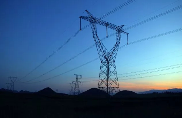
1. The effectiveness of DC withstand voltage test for finding defects in paper insulated cables
The DC withstand voltage test has been used to judge the quality of paper-insulated cables for decades. Practice has proved that the effect is good, and reliable data of its internal defects can be obtained. First of all, in the sense of measuring the DC withstand voltage and leakage current of the cable, under the action of the DC voltage, the voltage in the cable insulation is distributed according to the insulation resistance. When there are developmental local defects in the cable insulation, the DC voltage will most It is added to the undamaged part in series with the defect, so the DC withstand voltage test is easier to find the local defects of the cable than the AC withstand voltage test. The DC withstand voltage test and the DC leakage current measurement of the cable are different in their meaning. The DC withstand voltage test and the DC leakage current measurement are carried out at the same time, because in actual work, the two are complete in terms of wiring and equipment testing. identical. In general, the DC withstand voltage test is an effective method to check insulation dryness, bubbles, mechanical damage in paper insulation, and process wrapping defects; leakage current test is an effective method to check insulation aging and moisture.
The purpose of the DC withstand voltage test is to check the withstand voltage of the cable. It is more effective for finding local defects such as moisture and mechanical damage in the paper insulating medium, because the voltage in the insulating medium under DC voltage is distributed according to the resistivity. In the event of a defect, the voltage is mainly borne by the resistance of the undamaged medium connected in series with the defect part, making the defect easier to expose. It is more conducive to find medium defects. The breakdown strength of cable paper insulation under DC voltage is about twice that under AC voltage, so higher DC voltage can be applied to test the dielectric strength of the insulating medium. In many cases, the insulation of the cable is measured with a shaker, and the insulation breakdown occurs in the DC withstand voltage test. Therefore, the DC withstand voltage is an effective means to detect the defects of the high-voltage cable in the paper insulation.
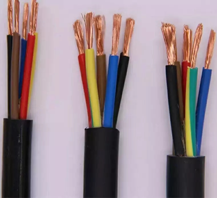
2. Limitations of DC withstand voltage test on XLPE insulated cables
Cross-linked polyethylene insulated cables have been widely used due to their excellent electrical properties, simple manufacturing process and easy installation. Has become a substitute for paper insulated cables. A general principle of high-voltage test, the test voltage field strength applied on the test product should simulate the operating conditions of high-voltage electrical appliances. The DC withstand voltage test is very effective for discovering the defects of paper insulated cables, but it is not necessarily effective for XLPE insulated cables, and it may have a negative effect, mainly in the following aspects:
1. The electric field distribution of XLPE insulated cables under AC and DC voltages is different. The XLPE insulation layer is made of polyethylene through chemical crosslinking. It is a monolithic insulation structure with a dielectric constant of 2.1-2.3 Less affected by temperature changes. Under AC voltage, the electric field distribution in the XLPE cable insulation layer is determined by the dielectric constant, that is, the electric field strength is distributed in inverse proportion to the dielectric constant, and this distribution is relatively stable. Under the action of DC voltage, the electric field strength in the insulating layer is distributed in direct proportion to the insulation resistance coefficient. The insulation resistivity distribution is not uniform, because a certain amount of by-products inevitably dissolve in the cross-linking process of the cross-linked polyethylene cable. They have relatively small insulation resistivity but are distributed in the radial direction of the insulating layer. Inhomogeneous, so the electric field distribution in the XLPE cable insulation layer under DC voltage is different from the ideal cylindrical insulation structure, which is related to the inhomogeneity of the material.
2. Cross-linked polyethylene insulated cables will accumulate unipolar charge under DC voltage. Once there is unipolar space charge caused by DC withstand voltage test, it will take a long time to release this charge. If the cable is left in DC Put into operation before the charge is completely released, the DC voltage will be superimposed on the peak of the power frequency voltage, making the voltage value on the cable far exceed its rated voltage, it will accelerate the insulation aging and shorten the service life, and serious insulation breakdown will occur.
3. The semiconductor protrusions and dirty spots of the XLPE insulated cables are prone to generate space charges. However, if surface flashover or cable accessory breakdown occurs during the test, it will cause wave oscillation in the cable core. Harm to the insulation of other normal cables and connectors. One of the Achilles’ heels of XLPE insulated cables is that water branches are easy to produce in the insulation. Once water branches are generated under DC voltage, they will quickly turn into electrical branches and form electrical discharges, accelerating the deterioration of the insulation water, so that the power frequency voltage is running. Under the action of the formation of breakdown.
4. The DC withstand voltage test cannot effectively find certain defects under the action of AC voltage. For example, in the cable accessories, if the insulation has mechanical damage and other defects, the insulation is most prone to breakdown under AC voltage, and it is often not possible under DC voltage. Breakdown occurred. Insulation breakdown under DC voltage often occurs in the part where insulation does not normally break down under AC working conditions. Therefore, the DC withstand voltage test cannot simulate the operating conditions of the high-voltage cross-linked cable, the test effect is poor, and there is a certain degree of harm, so the DC withstand voltage test has obvious shortcomings in detecting the defects of the cross-linked polyethylene insulated cable.
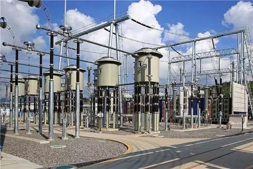
3. AC withstand voltage test
Since the DC withstand voltage test cannot simulate the operating field strength of the cross-linked polyethylene insulated cable and cannot achieve the desired test results, the AC withstand voltage test should be considered to detect the quality of cable laying and the installation of accessories. The following communication test methods should be used:
1. 0.1Hz ultra-low frequency voltage
According to the test capacity (the formula S=wCUs2=2∏fUs2KVA, where C-the cable capacity under test, Us- is the test voltage, f-power frequency, our country is 50HZ), it can be seen that 0.1Hz AC voltage Compared with the 50Hz voltage, the former requires 1/500 of the power required by the latter. Therefore, it can produce portable devices for on-site use without any problem. For this reason, the ultra-low frequency voltage originally developed for testing large rotating motors is a possible alternative to the DC voltage test of plastic insulated cables.
In the basic investigation and research, first, for various simulation configurations, the voltage load applied to the insulation equal to the test voltage (2 times U0) at 50 Hz when the frequency of 0.1 Hz is used is obtained. After being tried out in the field test of the cable, we began to consider adopting the ultra-low frequency technology in the current VDE standard for medium voltage cables. The recommended test level of 0.1Hz is 3U0. Compared with the test with 50 Hz, the breakdown at the weak point is significantly faster. The test duration of 60min is necessary in order to break down possible weak points during the test. This shows that the ultra-low frequency test equipment is feasible and effective.
2. Oscillating voltage pulse
The oscillating voltage pulse source is based on the recommended standard of the 21-09/2 working group of the international large power grid. This group conducted an investigation and study of alternatives to the DC voltage test of plastic insulated high-voltage cable facilities in the 1980s. According to the circuit deformation with or without polarity conversion, this voltage waveform avoids the space charge effect due to its change over time. In addition, this voltage waveform has the advantage that a relatively simple method used in the field can produce a high test level. Unlike its low-frequency method, it is suitable for high-voltage cable facilities.
These test methods have not been popularized in our country at present, we are still in the research stage in terms of hardware and software. In order to reduce the DC withstand voltage test of the XLPE power cable, the test items of the rubber-plastic insulated power cable of the power cable circuit in the "Preventive Test Regulations for Power Equipment" can be carried out: (1) Measure the main insulation resistance of the cable; (2) The insulation resistance of the outer sheath of the cable; (3) the insulation resistance of the inner lining of the cable; (4) the ratio of the copper shielding resistance and the conductor resistance; (5) the DC withstand voltage test of the main insulation of the cable.
In order to use the cross-linked polyethylene insulated power cable as the above four measurements, the grounding method of the metal layer of the cable accessory installation process must be changed. The armoring layer and copper shielding layer of the terminal should be separately grounded with insulated stranded wires. The cross-section of the grounding wire of the copper shielding layer should not be less than 25 square millimeters, and the cross-section of the grounding wire of the armoring layer should not be less than 10 square millimeters.
The grounding wire of the copper shielding layer in the middle head shall not be connected with the armoring layer. The armoring layer on both sides of the joint must be connected with another grounding wire, and it must be insulated from the copper shielding layer. The ground wire connecting the armor layer must have an outer sheath, which has the same insulation and sealing performance as the outer sheath of the cable. Through the above-mentioned test items, in order to grasp the insulation status of each part of the cable.
The voltage waveform of the AC withstand voltage test of the main insulation should be an actual sinusoidal waveform, and the frequency should be between 20 Hz and 300 Hz. When the reactor is fixed, the square of the resonance frequency is inversely proportional to the capacitance, and its expression is: W2C=1/L. In other words, when the power supply frequency changes by n times, the capacitance of the test product changes by n2 times; when the frequency is 45~65HZ, the frequency can be changed by 1.44 times. When the number of electric devices or inductance remains unchanged, the test product The maximum capacitance can be changed by 2.07 times; the selected frequency is 20~300HZ, the frequency can be changed more than ten times, when the number of reactors or inductance is unchanged, the maximum capacitance of the sample can be changed by 100 times. The test voltage is in accordance with the regulations in the revision of China Southern Power Grid's "Preventive Test Regulations for Power Equipment", and the test time is 1h. Or the test voltage adopts the cable U0 value, and the test time is 24h, either.
Note: For cables or their accessory equipment that have been in operation, after reinstallation, partial renewal or re-production, a lower test voltage can be used or the test time can be shortened. The test voltage value should be determined through negotiation. At this time, factors such as the number of years of cable operation, environmental conditions, past breakdown history and the purpose of this test should be considered.
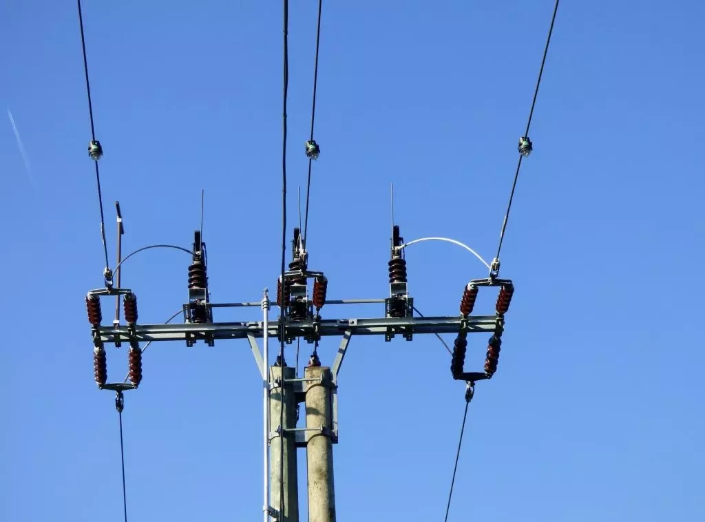
4. Analysis and judgment of test results
If the cable has passed the DC withstand voltage test without breakdown, the insulation of the cable can generally be considered qualified and can be put into system operation. But it does not mean that the quality of the cable that has passed the DC withstand voltage test is good. High-quality cable lines should be operated safely without accidents for decades under the condition of reasonable use and no external force damage. Below, the general criteria for judging the quality of power cable line insulation are as follows:
(1) If the cable has an insulation breakdown after the DC compensation voltage test, the system cannot be put into operation, and the fault point should be detected and repaired immediately.
(2) If the leakage current rises sharply with the increase of the test voltage, the system cannot be put into operation. The test voltage should be artificially increased to break the cable, and then the fault point should be detected and repaired.
(3) The leakage current value is very unstable (exclude external factors such as power supply voltage fluctuations). This may be caused by the partial discharge of the tiny air gap inside the cable insulation. At this time, the duration of the withstand voltage can be extended or the test voltage can be increased to observe the change of the leakage current. If the leakage current is not deteriorating in the case of delay or increase in voltage, the system can be put into operation and retest after 3 months.
(4) When the leakage current imbalance coefficient exceeds the specified standard, the influence caused by external factors should be eliminated first. When the leakage current imbalance caused by the internal defects of the cable insulation is confirmed, the extension in Article (3) above shall be adopted. Timely or increase the test voltage method for assessment, judgment and processing.
(5) When the leakage current has a rising trend with time, and the value of the leakage current increases significantly compared with the last time, the method of delay or increase the test voltage in the above article 3 can be adopted for assessment, judgment and processing.
(6) Short cables or other cables with weak defects can be put into system operation when the leakage current is too large and the leakage current value is stable and balanced. But it should be retested after 6 months.
(7) In the DC withstand voltage test, there is a small amount of flashover phenomenon, but the flashover phenomenon no longer occurs under the condition of delaying or increasing the test voltage, it is allowed to put the system into operation, but it needs to be retested after 6 October; if there is still flashover If the network phenomenon occurs, the fault point should generally be found and eliminated. Among the above items, the cables that need to be retested, and any cable that has no star deterioration trend in the retest result, can be put into system operation, and will no longer be included in the scope of the retest; if the retest result has a star deterioration trend, the reason should be found and given repair.
Concluding remarks
The DC withstand voltage test cannot effectively find the defects of the high-voltage cross-linked polyethylene main insulated cable, so it is not suitable for pre-testing. The AC withstand voltage test is an effective means to test the insulation quality of cross-linked cables. Accurate and effective grasp of the operating conditions of each part of the cable is conducive to improving the safe operation of the cable and reducing the failure of the cable during operation.


 Company Profiles
 Company Culture
 Message
 Honor
Honor Video Center
 Company Reality
 Pearl River Cable
 Low Voltage Cable
 Medium Voltage
 Mineral Cable
 Control Signal Cable
 Corporate News
 Cable Information
 Media Reports
 Network Reprint


