The advantages and disadvantages of the cross-linking process of the cross-linked cable and the three common production processes
1. Raw materials and semi-finished products for cross-linked cables
1. Conductor
The conductors of cross-linked cables are mostly round copper and aluminum stranded wires. There are also solid core conductors, and sector conductors can be used below 1kV.
Quality requirements for round single wires: smooth surface, no oil stains, no blackening, no bumps, no scratches, etc.
The conductor of the cross-linked cable must adopt a tightly pressed core. This is to prevent the shielding material and insulating material from being pressed into the stranded wire gap under the high temperature and high pressure in the cross-linked pipeline and causing waste; at the same time, it can also prevent the infiltration of water along the conductor direction, thereby preventing the generation and development of water branches. It can be seen that the compression process is a key measure to ensure the reliability of cable operation.
2. Insulating material
The insulating material used for cross-linked cables is: cross-linked polyethylene.
The general composition of cross-linked polyethylene is: polyethylene: antioxidant: cross-linking agent = 100: 0.3 to 0.5: 1.5 to 2.5.
In order to ensure the cleanliness of the insulating material (the products produced are qualified), the packaging must be intact and undamaged. Any insulating material with damaged packaging shall not be used.
For cross-linked cables of 35kV and above, ultra-clean materials are required.
3. Inner semi-conductive material
The inner shielding material is used for the conductor shielding of cross-linked cables. The long-term working temperature is 90℃, and the volume resistivity at 20℃ is not more than 1×10³ (Ω·cm).
There are two types of inner shielding materials: cross-linked and non-cross-linked. The cross-linked type can avoid the deformation of the inner shield or the flow of the conductor gap during overload or short circuit. The processing and extrusion of non-cross-linked materials are very convenient.
4. External semi-conductive material
The outer shielding material is used for insulation shielding, and the temperature resistance grade is consistent with that of the insulating material.
The outer shielding material is divided into three types: easy-peeling type (peeling strength of 8-20 Newtons/10 mm), peelable type (peeling strength of 20-40 Newtons/10 mm) and non-peeling type. For cross-linked cables of 26/35kV and below, easy-to-peel or peelable external shielding materials are required for the convenience of construction. For cross-linked cables above 26/35kV, non-peelable external shielding materials should be used.
5. Sheath material
The outer sheath of the cross-linked cable should generally be made of polyvinyl chloride cable sheath material with a temperature resistance of 90 ℃, which is consistent with the working temperature of the cable.
6. Shielding copper tape
Cables with a rated voltage greater than 0.6/1kV should have a metal shield. The metal shielding layer generally uses copper tape (more common) or copper wire (rare). The metal shielding layer can not only ensure that the insulation shield is at the ground potential (neutral point), but also allows the ground fault current to pass.
7. Armored steel tape/wire
The armor layer of the cross-linked cable generally uses steel tape or steel wire. The steel tape armor layer can withstand radial pressure, and the steel wire armor layer can withstand axial tension.
The armored steel of the cross-linked cable has two types: painted steel strip and galvanized steel strip.
8. Inner lining
The inner lining mainly plays a role of tightening when forming a cable. The material requirements are not easy to absorb moisture and have a temperature resistance level matching the insulating layer. Polyvinyl chloride tape, polyester tape, non-woven tape, etc. can be used.
9. Isolation sleeve
The isolation layer is to prevent the metal shielding layer (copper) and the outer armor layer (steel) from forming galvanic cells and accelerating corrosion. Therefore, the isolation layer of the armored cross-linked cable must be an impermeable extruded isolation sheath. Generally, the same PVC sheath material as the sheath is used.
10. Filling
The filling is to make the cable round after being cabled. The material requirements are not easy to absorb moisture and have a temperature resistance level matching the insulating layer. Class A flame-retardant cables use asbestos rope, and other cables use ordinary filler rope.
2. Interconnection Group (Introduction)
1. Take-up and release line
In order to ensure the continuity of production, it is best to adopt double receiving and double releasing. Of course, the storage device (generally can store more than 100 meters) is indispensable. The take-up and pay-off line mostly adopts the gantry type, and some adopt the earth axis type.
2. Upper traction
The upper traction requires high friction, stable traction, uniform speed, and no "skidding" to ensure the stability of the drape control.
Most domestic use single traction sheaves with a diameter of over 1500mm and a speed adjustment range of 1.2-20 m/min. In order to increase friction, a belt is attached to the traction sheave to compress the wire.
3. Extruder
The extruder is composed of barrel, screw, head and transmission part.
The barrel is made of cemented carbide, and the material hardness is required to reach 75-76 Rockwell. Oil heating is better for barrel heating-temperature control is more stable than electric heating, but the heating system is complicated and the heat loss is more.
The screw is made of stainless steel or nitrided steel, and the hardness is slightly lower than that of the barrel, generally Rockwell 65 or so.
The fuselage and screw should have forced cooling capacity, the fuselage can be air-cooled, and the screw can be water-cooled.
Due to the large extrusion viscosity (especially the outer shielding material), the extrusion load is large, and it is best to use a pressure gauge to monitor the extrusion pressure.
⑴ Inner shield extruder
Due to the small amount of internal shielding structure, a Φ65 machine is generally used.
There are many fillers in the inner shielding material, and the friction heat during the extrusion process is relatively large. Therefore, the screw should not be too long. Generally, the length to diameter ratio is 20:1, the compression ratio is 3:1, and the speed range is 10-60 rpm. About points.
In addition, it is best to install automatic feeding and pre-drying devices.
⑵ Insulation extruder
Due to the large amount of insulating layer structure, Φ150 machines are generally used.
The screw length-to-diameter ratio is generally 25:1, the compression ratio is 2.5:1~3:1, the speed range is about 9~45 rpm, and the glue output should reach more than 200 kg/hour.
In addition, it is best to install automatic feeding and pre-drying devices.
⑶ External shielding extruder
The amount of structure of the outer shield is slightly larger than that of the inner shield, and a Φ90 machine is generally used.
Generally, the length to diameter ratio is 20:1, the compression ratio is 3:1, and the speed range is about 14 to 41 rpm.
⑷ Machine head
1+1+1 nose: too backward has been eliminated. 1+2 nose: more common now. 0+3 head: less, advanced.
The use of 1+2 head or 0+3 head makes the contact between the layers close, eliminates air gaps, avoids interlayer pollution, and improves the electrical performance of the cable.
4. Cross-linked tube
Since the cross-linked pipe is subjected to high temperature and high pressure (force), seamless steel pipes should be used, preferably stainless steel pipes, with a pipe diameter of 200-300mm.
Cross-linked tubes can be divided into two types: catenary type and vertical type. The length is about 120 meters and 100 meters respectively. The vertical eccentric core is easy to control, but the cost is relatively high.
The heating of the cross-linked tube is mostly transformer heating (dry method), and the wall of the cross-linked tube is used as the secondary circuit of the transformer, and its thermal efficiency is very good.
5. Pull down
In order to ensure the stable operation of the traction, it is best to use two tractions for the lower traction. The first is a traction wheel, and the second is a crawler traction.
6. Water vapor and electrical control part
Water and air control can be divided into automatic and manual. They are generally installed near the nose and controlled by the captain.
The electrical control part is divided into centralized control (master console) and decentralized control (each control panel).
7. Instrument operation and maintenance regulations (different with equipment)-slightly
3. Cross-linking process
1. Basic principles of cross-linking
In order to improve the temperature resistance of polyethylene, we can use chemical or physical methods to make it into a body-shaped molecular structure, which is called cross-linking.
Chemical cross-linking is to add a certain amount of cross-linking agent (usually dicumyl peroxide-DCP) to polyethylene, which quickly decomposes to form free radicals when heated to a certain temperature, and the free radicals are unstable, which deprives polyethylene The hydrogen in the molecule turns polyethylene molecules into macromolecular free radicals, and their mutual combination forms a body-shaped molecular structure.
2. Crosslinking degree and process parameters
The degree of cross-linking is an important indicator of the thermal performance of a cable. Generally, the thermal extension method is used for measurement (20 Newton/cm load at 200°C, elongation at 15 minutes).
⑴ Temperature
The cross-linking process is completed in the heating section of the vulcanized tube. The higher the temperature of the vulcanized tube, the higher the degree of cross-linking (when other factors remain unchanged). Generally speaking, considering various factors, the temperature of the vulcanization tube for dry crosslinking should be around 290~310℃.
⑵ Linear speed
Obviously, the higher the line speed, the higher the production efficiency, but the degree of crosslinking will be lower (when other factors remain unchanged). Generally speaking, the line speed is controlled by the following factors:
① Rated voltage: The higher the voltage, the thicker the insulation and the slower the cross-linking speed, so the line speed is more restricted.
② Cable specifications: the larger the cross-section, the larger the amount of glue output from the extruder is required, so the line speed cannot be too fast.
③ Cooling water temperature and water level: low cooling water temperature and high water level are good for cooling, but not good for cross-linking.
④ Vulcanization tube: The higher the temperature and the longer the pipeline, the faster the line speed.
⑶ Extrusion temperature
The extrusion temperature mainly depends on the formulation of the raw materials. The extruded material is required to be fully plasticized and not cross-linked in advance.
3. Extrusion of shielding and insulating layer
⑴ Extrusion of inner shielding layer
l Extrusion temperature
The inner shielding material is divided into two types: cross-linked and non-cross-linked. The former requires higher temperature control. Due to different materials and equipment, the extrusion temperature is also different. But the selection principle of extrusion temperature is:
① General principle: The extruded material is required to be fully plasticized and not cross-linked in advance.
② Feeding section: The temperature should not be too high. In order to avoid premature softening or adhesion of the pellets, resulting in reduced or uneven glue output.
③ Rubber tube: The temperature should not be too low. Otherwise, the body pressure is too high and the equipment is easily damaged.
Inner shield extrusion reference temperature (±5℃)
Extruder part | Machine body | Lead hose | Machine head | ||||
1 | 2 | 3 | 4 | 1 | 2 | 1 | |
Temperature range (℃) | 95 | 105 | 110 | 115 | 115 | 115 | 115~120 |
Since the elongation of the inner shielding material is small, the extrusion requirements are tight, and the surface is required to be round, an extrusion die is used.
The inner shielding layer should be uniform, the surface should be smooth, without obvious twisting lines, and there should be no sharp corners, particles, burnt or scratch marks. The thickness is subject to good manufacturability and reasonable economy, generally 0.5~0.8mm.
l Mold selection (extrusion type)
Core aperture of the inner shielding layer D1 = conductor diameter d + (0.3~0.6)
If the aperture is too large, it is easy to cause eccentricity; if the aperture is too small, it is easy to produce slubs.
Inner shielding layer mold sleeve aperture D2 = conductor diameter d + 2 × inner shielding layer thickness t1
⑵ Extrusion of insulation layer
l Extrusion temperature
The insulating material is cross-linked polyethylene. Due to different materials and equipment, the extrusion temperature is also different. The selection principle of the extrusion temperature is the same as that of the inner shielding layer.
Inner shield extrusion reference temperature (±5℃)
Extruder part | Machine body | Lead hose | Machine head | |||||
1 | 2 | 3 | 4 | 5 | 1 | 2 | 1 | |
Temperature range (℃) | 95 | 100 | 105 | 110 | 113 | 115 | 115 | 115~120 |
The insulating layer is required to be free of bubbles, impurities, etc.; the average value of the six points of thickness is not less than the nominal value, and the thinnest point is not less than 90%-0.1 of the nominal value.
l Mold selection (extrusion type)
Insulation layer core aperture D3 = inner shielded diameter D2 + (0.5~0.8)
If the aperture is too large, the insulation is likely to form "ears"; if the aperture is too small, it is easy to scratch the inner shielding layer.
Insulation layer mold sleeve diameter D4 = inner shielded diameter D2 + 2 × insulation layer thickness t2 + 2 × mold core mouth thickness δ
For three-layer co-extrusion equipment:
Insulating layer core aperture D3 = inner shielding layer die sleeve aperture D2
Insulation layer mold sleeve diameter D4 = inner shielded diameter D2 + 2 × insulation layer thickness t2 + 2 × mold core mouth thickness δ
⑶ Extrusion of the outer shielding layer
l Extrusion temperature
The outer shielding layer adopts semi-conductive insulating shielding material. Due to different materials and equipment, the extrusion temperature is also different. The selection principle of the extrusion temperature is the same as that of the inner shielding layer.
Inner shield extrusion reference temperature (±5℃)
Extruder part | Machine body | Lead hose | Machine head | |||||
1 | 2 | 3 | 4 | 5 | 1 | 2 | 1 | |
Temperature range (℃) | 90 | 100 | 105 | 110 | 110 | 115 | 115 | 115~120 |
The outer shielding layer should be uniform, the surface should be smooth, without obvious twisting lines, and there should be no sharp corners, particles, burnt, or scratch marks. The thickness is subject to good manufacturability and reasonable economy, generally 0.5~0.8mm.
l Mold selection (extrusion type)
The core diameter of the outer shielding layer D5 = the diameter after insulation D4 + (0.5~0.8)
If the aperture is too large, it is easy to cause eccentricity; if the aperture is too small, it is easy to produce slubs.
Outer shielding layer mold sleeve aperture D6 = After insulation diameter D4 + 2 × outer shielding layer thickness t2 + 2 × mold core mouth thickness δ
For three-layer co-extrusion equipment:
Outer shielding layer core aperture D5 = insulating layer die sleeve aperture D4
Outer shielding layer mold sleeve aperture D6 = After insulation diameter D4 + 2 × outer shielding layer thickness t2 + 2 × mold core mouth thickness δ
4. Cross-linking process (dry method)
The dry cross-linking equipment is basically the same as the wet cross-linking equipment, except that the heating method of the cross-linking pipeline is different. The dry cross-linking uses electric heating and radiation heating.
The temperature of the dry cross-linking pipeline is closely related to the linear velocity, the length of the heating section of the pipeline, the length of the cooling section, and the specifications of the cable.
Reference table for temperature control range of heating section of cross-linked pipe (±10℃)
Pipe area | 1 | 2 | 3 | 4 | 5 | 6 |
Temperature range(℃) | 340 | 330 | 320 | 300 | 270 | 240 |
Because of the high heating temperature of dry cross-linking, the polymer will undergo oxidative degradation, so it needs inert gas to protect it. Nitrogen is widely used due to its abundant sources and low price.
Cross-linked shielding materials, especially insulating materials containing cross-linking agent (dicumyl peroxide), decomposition products and cross-linking by-products at high temperature and other small molecules will become gas, if there is no pressure control, Larger bubbles will be formed, so the crosslinking reaction must be carried out under pressure, generally 0.7~1.2MPa.
5. Start parking procedure
⑴ Preparation before driving
① Select the closed pad and mold matching: prepare the upper and lower closed pads and molds according to the cable specifications to be produced, and install the machine.
② Heating and heat preservation of the extruder: In order to make the temperature of the extruder meet the technological requirements, the temperature should be raised 3 to 4 hours in advance.
③ Thread the traction line: draw the traction line from the upper to the lower seal, wind it on the lower traction sheave, and connect it to the take-up reel.
④ Conductor joint: hydraulically connect the conductor and the lead with a joint steel pipe (preferably copper pipe), the pay-off reel is raised in place, the tension is appropriate, and the cord reservoir is full of conductors.
⑤ Traction and wire take-up: select up and down traction, auxiliary traction, and wire take-up gears according to process requirements.
⑥ Drying of the shielding material: The shielding material should be dried before use at a temperature of 40 to 60°C for more than 4 hours.
⑦ Take-up: select the take-up reel according to the planned length, adjust the cable pitch, limit, and the angle of the cable guide wheel.
⑵ Driving
① Wire routing: adjust the up and down traction and synchronize them.
② Tension adjustment: adjust the traction to make the wire tension appropriate, and put it into the suspension controller. When the suspension controller indicates zero or does not swing too much, it means that the tension is adjusted well. Adjust the tension of the retractable line.
③ Start the extruder: start the inner shielding machine first after routing the wires, and start the insulation and outer shielding machines separately after adjustment. When the thickness of each layer and the appearance quality of the eccentricity are adjusted, (after the traction line is out of the lower seal), it will be lowered. Close and seal.
④ Water and air process: Turn on the water pump to make the cooling water enter the cooling pipeline.
⑤ Seal the sealer: After the extruder is adjusted, the sealer can be sealed.
⑥ Cross-linking pipe heating: heating the pipe according to the given process temperature.
⑦ Nitrogen supply: Nitrogen is supplied according to operating procedures and technological regulations.
⑧ Finished product mark: When the temperature and pressure meet the process requirements, mark the bottom seal, and X (60) meters later is the finished product.
⑨ Start-up is complete: Put the finished product line on the line tray, adjust the speed and line pitch, and transfer to normal production.
⑶ parking
① Stop the heating power supply of the cross-linked tube.
② Stop feeding the extruder respectively.
③ Adjust the water level to the highest position of the control range.
④ Stop the nitrogen supply, reduce the speed of the extruder, reduce the outer diameter of the cable, and release the nitrogen. When the nitrogen is exhausted, the entire line will stop.
⑤ When the pressure in the pipeline is zero, open the interlocking device and the upper seal.
⑥ Mark the finished product and take the insulated waste wire out of the pipeline.
⑦ Stop the water pump and drain the cooling water.
⑧ The extruder is cleaned according to regulations.
⑨ Close all switches and valves.
Fourth, the causes of quality defects and troubleshooting methods
Types of cross-linked waste products and their causes and solutions
Waste category | Phenomenon | cause | Solution |
Insufficient insulation thickness | The thinnest point is below the standard, The average value is lower than the nominal value | Fast line speed, Insufficient glue output from the extruder, Improper mold matching. | Reduce the line speed, The speed of the extruder increases, Reasonable matching of molds. |
Partial core | Uneven thickness of insulating layer | The mold is not adjusted, Drape control change | Adjust the mold, Try to control the drape as stable as possible |
Impurities | Pimple on the line | The raw materials are dirty, mixed in when adding, Scorch | Choose good materials, clean the materials, and control the extrusion temperature. |
Air bubble | There are pores on the insulation slice | Improper extrusion, wet material, insufficient cooling (on the same circumference) | Reasonably match the mold, bake the material, increase the water level or reduce the cooling water temperature. |
Scratches on the surface | The surface is not smooth, Scratched | Wipe the wall in the vulcanized tube, There is burnt on the outer edge of the mold sleeve. | Adjust the drape, clean up foreign objects in the pipeline in time to prevent the mold sleeve from overheating, and stop the machine to clean the mold sleeve. |
Bamboo knot | The outer diameter varies in size. | The traction speed is unstable, The core is too small, The outer diameter of the conductor is not uniform. | Check the mechanical and electrical system failures and eliminate them, appropriately adjust the size of the mold core, and control the outer diameter of the stranded wire. |
Unqualified mechanical properties | Poor thermal-mechanical properties, The working temperature cannot be reached. | The formula is unreasonable, Improper vulcanization process (low air pressure, fast line speed, high cooling water level, etc.). | Adjust the formula, Find out the specific reasons and eliminate them one by one. |
Unqualified electrical performance | The bureau is overvalued, Insulation breakdown | Imperfect structure (conductor, insulation), impurities in the insulation layer, trauma | Make the conductor round and smooth, standardize the operation, clean the material, and prevent bumps |
5. Product experiment and inspection
1. Routine test
Routine test is factory test. That is, each cable needs to be tested. It includes the following items:
⑴ Conductor DC resistance test
Executive standard: GB/T 3956
⑵ Partial discharge test
Executive standard: GB/T 3048.12. The partial discharge of each phase should not exceed 10pC under 1.73U0.
⑶ AC voltage test
Executive standard: GB/T 12706.2. Each phase withstands power frequency voltage for 5 minutes without breakdown.
AC voltage test value
Rated voltage(U0 kV) | 3.6 | 6 | 8.7 | 12 | 18 | 21 | 26 |
Test voltage (kV) | 12.5 | 21 | 30.5 | 42 | 63 | 73.5 53 | 91 65 |
When a three-phase transformer is used to conduct a voltage test on a three-core cable at the same time, the voltage should be 1.73 times the value in the table.
2. Sampling test
⑴ Structure and size inspection
① Conductor structure size: should meet the relevant regulations of GB/T 3956.
② Insulation thickness: the average value is not less than the nominal value, and the minimum value is not less than 90%-0.1 of the nominal value.
③ Sheath thickness: the average value is not less than the nominal value, and the minimum value is not less than 85%-0.1 / 80%-0.2 of the nominal value.
⑵ Four-hour AC voltage test
This test is applicable to cables above 3.6/6 kV. The length of the sample is not less than 5 meters, and the test voltage is applied to each phase for 4 hours. The test voltage is as follows:
Four-hour AC voltage test value
Rated voltage(U0 kV) | 6 | 8.7 | 12 | 18 | 21 | 26 |
Test voltage (kV) | 24 | 35 | 48 | 72 | 84 | 104 |
The insulating material of the cross-linked cable is XLPE, and its base material is PE and other ingredients, and the cross-linking process is to form a body-shaped network branching structure by using a polyethylene (PE) material with a linear molecular structure through a specific processing method. XLPE.
The long-term allowable operating temperature is increased from 70°C to 90°C (or higher), and the short-circuit allowable temperature is increased from 140°C to 250°C (or higher). While maintaining its original excellent electrical performance, it has greatly improved Actual performance.
Cross-linking method of cross-linked cable
There are many cross-linking methods for cross-linked cables. At present, the commonly used cross-linking methods include peroxide chemical cross-linking (ie DCP cross-linking), silane cross-linking and radiation cross-linking. Among them, silane cross-linking is divided into different materials. For warm water crosslinking and boiling-free silane crosslinking. No matter which cross-linking method is adopted, the result of cross-linking is that the thermal extension of the cross-linked cable meets the performance requirements of the national standard.
1. Chemical crosslinking
The DCP cross-linking production line uses catenary or tower equipment, and the equipment and plant cost are high, and it needs to consume a lot of water, electricity, gas, etc., so the investment is relatively large; because the production line is longer, it is only suitable for the production of large-length cables; High environmental requirements require specialized production workshops.
2. Silane crosslinking
The silane cross-linking production line only needs ordinary extruder and heating device (hot pool or steam room), low investment, low environmental requirements, flexible production, suitable for the production of long or short cables, and can be manufactured in different lengths according to customer needs Cables.
3. Irradiation crosslinking
Irradiation cross-linking, irradiation cross-linking is to use the high-energy electron beam generated by the electron accelerator to bombard the insulating layer and the sheath to break the polyethylene (PE) material polymer chain with linear molecular structure. A breakpoint becomes a free radical. Free radicals are unstable and must be recombined with each other. After recombination, the original chain molecular structure becomes a three-dimensional network molecular structure to form crosslinks.
In addition, the radiation dose applied in the production process of radiation cross-linking leaves a large safety margin from the destruction dose. The radiation damage dose of polyethylene is 1000KGY, and the processing dose is about 200KGY. In addition to the improvement of the special formula, it is still cross-linked by radiation in a relatively wide range, so its performance will be affected by radiation during a long period of use. improve. Type of radiation cross-linked cable: YJ(F)-(irradiation) cross-linked polyethylene insulation, F: irradiation.
Comparison of three cross-linking methods
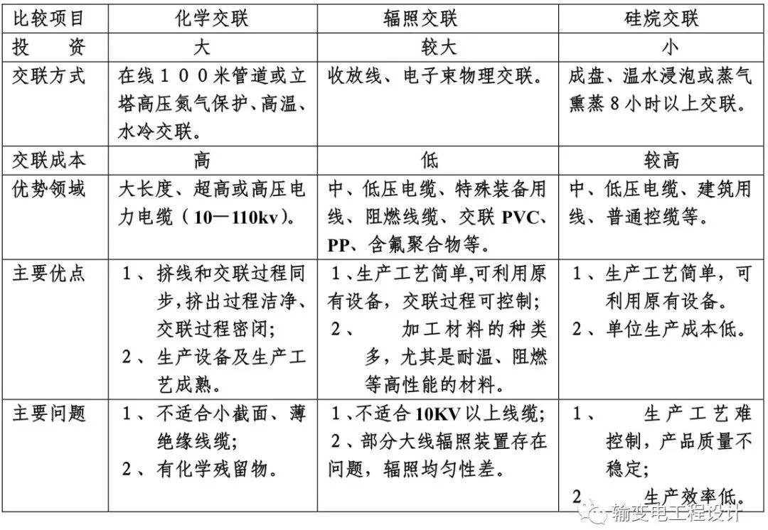
Cross-linked cables have been widely used because of their high temperature resistance, strong overload resistance, good physical and mechanical properties, and long service life.
The cables produced by three cross-linking methods: peroxide chemical cross-linking, electron beam irradiation cross-linking, and silane warm water cross-linking, coexist in the cross-linked cable market.
It can be seen from the above table that due to the particularity of the chemical cross-linking production process, there are irreplaceable advantages of other cross-linking methods in high-voltage resistant, large cross-section cables; medium and low-voltage ordinary cross-linked cables, radiation cross-linking, warm water Cross-linking competition has become a reality; however, radiation cross-linking has unique advantages in high temperature resistance, flame-retardant, and cross-linking of polymers other than polyethylene materials.


 Company Profiles
 Company Culture
 Message
 Honor
Honor Video Center
 Company Reality
 Pearl River Cable
 Low Voltage Cable
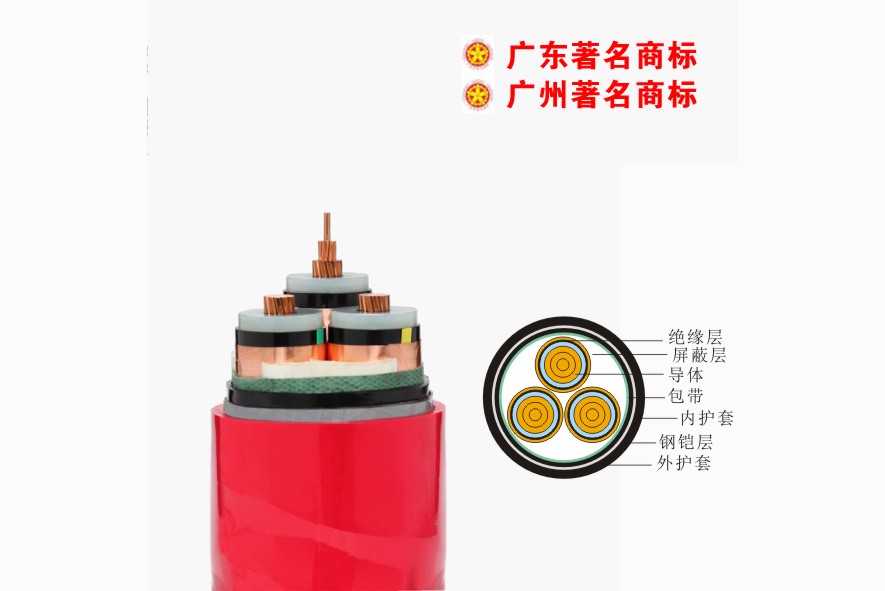 Medium Voltage
 Mineral Cable
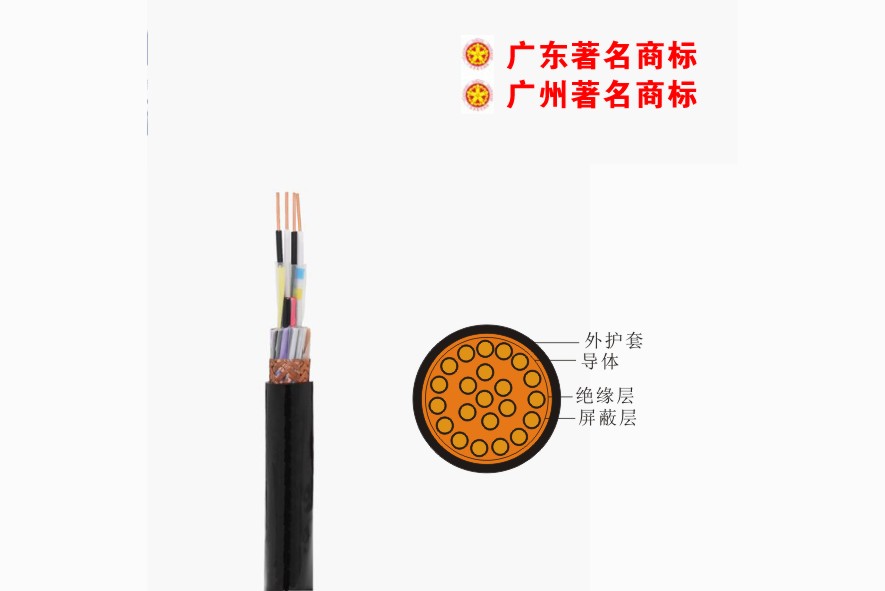 Control Signal Cable
 Corporate News
 Cable Information
 Media Reports
 Network Reprint


