Technical requirements for laying of wires and cables in common engineering
Technical requirements for laying of wires and cables in common engineering
1. Technical requirements for wire connection
2. Color marking of insulated conductors or bare conductors in the line
Third, the laying requirements of power cables
Fourth, the type of commonly used wire
5. Laying of commonly used cables
1. Technical requirements for wire connection
1. The crimping method should be adopted for the connection of the wire in the box or the box. Terminals and copper (aluminum) sleeves, clamps, etc. can be used for connection. The copper core wire can also be connected by winding and tinning; single strand aluminum The core wire should be connected by insulated screw connection buttons, and welding connection is forbidden.
2. The connection between the wire and the terminal of the electrical appliance
Single-strand copper (aluminum) core and multi-strand copper-core wires with a cross-section of 2 mm2 and below can be directly connected, but the core of multi-strand copper-core wires should be tightened first. Connect after enamelling.
Multi-strand aluminum-core wires and multi-strand copper-core wires with a cross-section of more than 2.5 mm2 should be crimped to the terminals and then connected to the terminals of electrical appliances (except for the plug-in terminals that come with the equipment).
3. Reliable transition measures should be taken for the connection of copper and aluminum wires. Copper and aluminum transition terminals, copper and aluminum transition sleeves, copper and aluminum transition clips, etc. can be used for connection. Copper and aluminum terminals should be tinned when connecting copper and aluminum terminals. deal with.
4. When using the crimping method to connect the wires, the specifications of the copper (aluminum) bushing and die of the terminal should be consistent with the cross-section of the core.
5. Acid flux should not be used when tinning copper core wires and copper terminals.
2. Color marking of insulated conductors or bare conductors in the line
1. AC lower phase line:
L1. The phase is yellow; the L2 phase is green; the L3 phase is red; the neutral wire is light blue; the protective ground wire (PE wire) is yellow and green.
2. DC line: the positive pole (+) is brown; the negative pole (one) is blue; the grounding neutral line is light blue.
3. The green and yellow two-color wire is only used to mark the protective grounding and cannot be used for other purposes. Light blue is only used for the neutral or middle line.
4. The color mark can be marked on the entire length of the conductor with the specified color or the insulation color of the insulated conductor, or it can be marked on the selected easily recognizable position (such as the end or the accessible part).
3. the laying requirements of power cables
1. Before laying, calculate the length of each cable according to the design and actual path, arrange each cable reasonably, and reduce cable joints.
2. Reliable safety measures should be taken for laying cables in live areas.
3. The power cable should have a spare length near the terminal head and the joint.
4. The distance between the supporting points of the cable should meet the design regulations. When the design is not specified, the length shall not be greater than the value listed in Table DQ5-1.
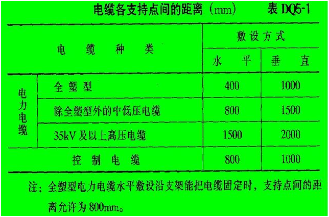
Distance of cable support point
5. The minimum bending radius of the cable should meet the requirements of Table DQ5-2.
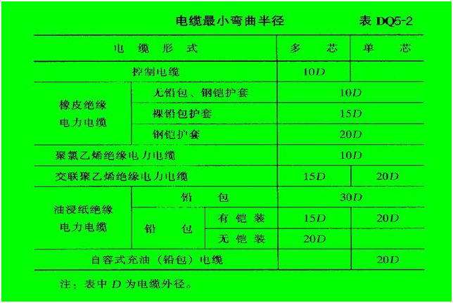
Cable minimum bending radius table
6. When laying the cable, the cable should be led out from the upper end of the reel, and the cable should not be dragged by friction on the support and the ground. The cable shall not have any unremoved mechanical damages such as flattening, twisting of the cable, or breaking of the sheath.
7. The layout of power cable joints should meet the following requirements:
1) For cables laid side by side, the positions of their joints should be staggered with each other.
2) The joints of the cable should be fixed with a pallet.
3) There should be a protective box to prevent mechanical damage outside the directly buried cable joint box (except the epoxy resin joint box). The protective box located in the frozen soil layer should be filled with asphalt.
8. When laying cables, they should be neatly arranged, not crossed, fixed, and signs should be installed.
9. The installation of the sign board should meet the following requirements:
1) Cable terminals, cable joints, bends, mezzanine, both ends of tunnels and shafts, manholes, etc., shall be equipped with signs on the cables.
2) The line number should be indicated on the sign. When there is no serial number, the cable model, specification and starting and ending location should be stated; the cables used in parallel should have a serial number. The handwriting of the sign board should be clear and not easy to fall off.
3) The specifications of signs should be unified. The sign board should be anticorrosive, and the hanging should be firm.
10. The cables should be fixed in the following places:
1) Vertical laying or more than 45. Cables laid obliquely on each support; every 2m on the bridge;
2) For cables laid horizontally, at the first and last ends of the cable and at both ends of the turn and the cable joint; when the cable spacing is required, every 5-10m;
3) The fixing of single-core cables should meet the design requirements.
11. In the following locations, the cable should have a protective tube with a certain mechanical strength or a protective cover:
l) Cables enter buildings, tunnels, through floors and walls.
2) The section leading from the channel to the poles, equipment, the outer surface of the wall or the place where pedestrians in the house can easily approach, and the height below 2m from the ground.
The depth of the protection pipe buried in the non-concrete ground shall not be less than 100 mm; the length of the protruding water slope of the building shall not be less than 250 mm. The root of the protective cover should not be higher than the ground.
12. The following measures should be taken to prevent fire and flame retardancy of cables:
1) When the cable passes through the shaft, wall, floor or into the hole of the electrical panel or cabinet, seal it tightly with fire-proof plugging material.
2) In important cable trenches and tunnels, install fire barriers in sections or use soft refractory materials as required.
3) For important circuits, it can be laid separately in a special channel or in a fire-resistant enclosed tank, or fire-resistant paint can be applied to it
4) Apply fire-resistant paint or fire-resistant tape on both sides of the power cable joint and adjacent cables 2 to 3m in length.
5) Use fire-resistant or flame-retardant cables.
6) Set up alarm and fire extinguishing devices.
13. When plugging cable holes, the plugging should be firm and reliable, and there should be no obvious cracks and visible pores. If the holes are larger, refractory lining should be added before plugging.
4.commonly used wire models
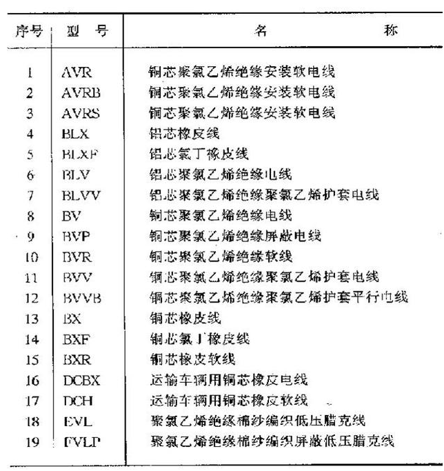
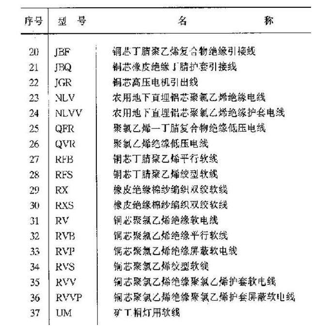
Common wire model
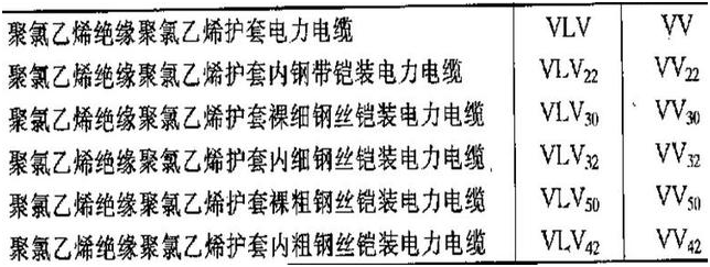
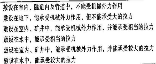
Five, commonly used cable models



 Company Profiles
 Company Culture
 Message
 Honor
Honor Video Center
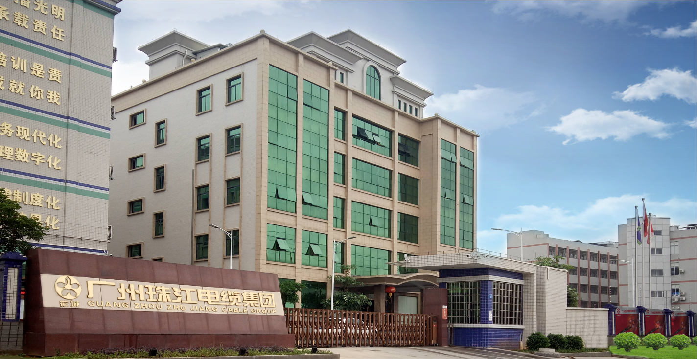 Company Reality
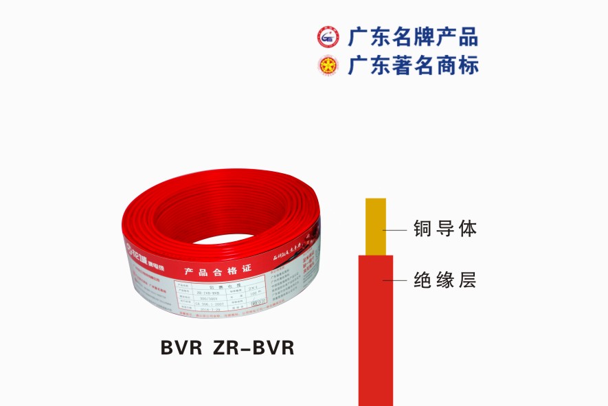 Pearl River Cable
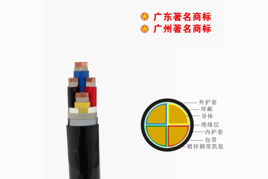 Low Voltage Cable
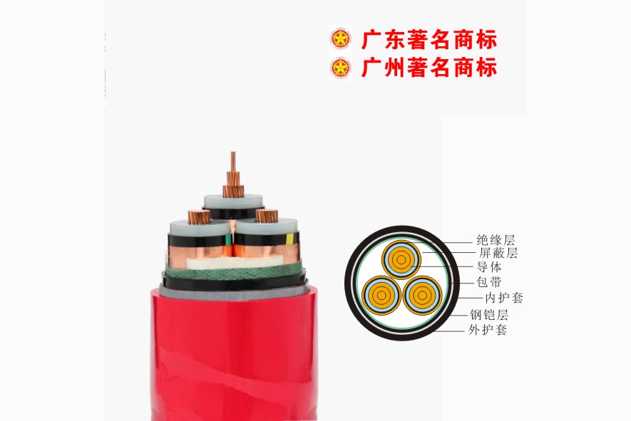 Medium Voltage
 Mineral Cable
 Control Signal Cable
 Corporate News
 Cable Information
 Media Reports
 Network Reprint


